PID
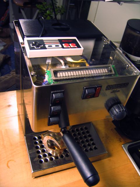
A microchip PIC16F876 gets temperature readings from a boiler-top mounted National LM34 Temperature Sensor. These temperature readings are processed using the PID control loop which I learned about in detail from the excellent article PID with out a PhD. A thrift store modder's favorite NES controller can set the PID gains, espresso and steam setpoints, temperature calibration values, and heater control PWM period. I wrote the NES code by reading a fantastic spec available from the iGamePlay project. The NES gamepad's popularity is well deserved as is a tough little controller with enough buttons to be useful, yet still very simple. For example, the select button switches between the main mode and setup mode, and the arrow buttons allow you to choose and alter variable values. It works out pretty cleanly. The main display currently shows a) the current temperature, b) the heater power setting (0 - 100 percent, which translates to a PWM heat amount), c) a timer showing how long the machine has been heating up, and d) a timer that alternates between a shot timer, and a timer showing how long the machine has been temperature stable and ready (remaining within 0.5 degrees of the set point).
One of the most interesting challenges so far has actually been tuning the PID loop. Currently though, after it settles, the machine appears to be indefinitely stable (I've seen it stable for over 2 hours before shutting off the machine) to about 0.1 degrees of the set point temperature. Interestingly, stability improved substantially after I finally closed the machine back up (after easily a year of being in terminal state of "operational dissassembly") and insulated the boiler from room drafts etc.
Shot Timer
One of the big motivations to go the distance and give the PIC total machine control was to enable a shot timer. When the top switch is thrown, it starts counting the seconds. It was basically a lot of work to make the machine act like it always does, but just so the PIC knows about it. The front panel switches are all "virtual" just pulling pins on the microcontroller which in turn throws the relays. One cool side effect of this is that starting a shot no longer makes a click sound on my stereo speakers. I think this is because the zero-crossing relays remove the spark-gap that occurs with a normal 120 switch (that's just a guess, but something changed because the grinder switch still sends out an electric 'pop' . . . for now).
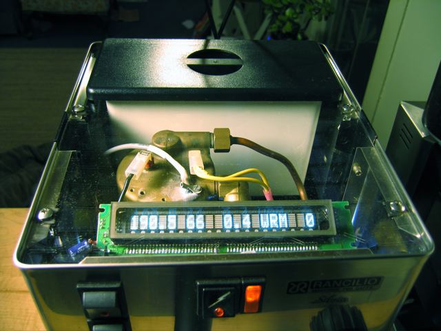
A closeup of the VFD display showing a slightly outdated version of the interface.
Remote Control
Once I had the PIC sitting between the switches and the relays, and I had a NES controller setup to change PID values, my inner (or is that outer?) nerd forced me to add a useless "remote control" feature that replicates the front panel switches with the A, B, and start buttons on the gamepad. Eventually, I would like to put a solenoid on the steam wand valve so that I can call for water and steam completely with buttons and switches, and get rid of the squeeky knob (btw, does anyone know how to lubricate the steam valve with something more edible than WD-40?).
Bling
A combination 5v/12v power supply left the door open for some code cathode lights to sit on the 12v rail. While there is some utility in adding light under the brew head, this is mostly just silliness-- especially my "ground effects." A laser cut clear acrylic top allows for the VFD display to be viewable without undermining the sleek boxy shape of the Silvia.
While there are still quite a few wires swimming around under the top, the overall number has been reduced, and it makes for a fairly clean appearance from above. I removed both top-mounted thermostats, and the switches have only 2 wires each instead of 4 going to each switch. Sadly, the little switch lights don't work. Though perhaps its possible to get them back?
Plumbing
I also drilled and plumbed a drain from the bottom of the drip tray. The plumbing technique was the great idea of a clever hardware store employee who showed me to the lamp parts section. The key ingredients are a threaded tube and low profile gnurled nut. A tube feeds a growler under the table and greatly reduces the number of spills from an overflowing drip tray. I am the kind of person who forgets to fill the water tank and empty the drip tray., so I really like this mod. I used to have the intake plumbed out to a remote water tank as well. It was great to be able to see the water level (a feature I hope to add for the internal tank), but ultimately it doesn't look as clean and the internal reservoir gives a little preheat to the water as well (Has anyone tried preheating their water out there, perhaps with a fish tank heater?). Heres two pics of the drain plumbing.
 A view down into the tray. I've since trimmed the top off the tube coming into the tray.
 Underneath the drip tray, taking advantage of a factory access hole in the bottom of the machine.
Some Guts
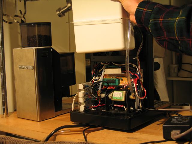 I had originally planned to make space for the power supply and electronics by remoting the water tank, but everything ended up fitting. The electonics was luckily simple enough that I could just solder it all on a perf-board instead of needing a real circuit board (which would still be cool, especially if one were to make more of these...)
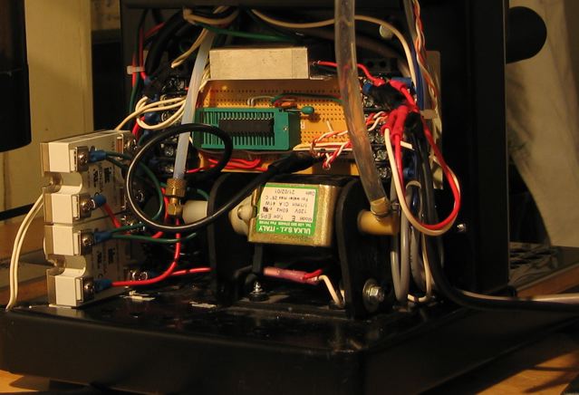 Screw terminals on both ends of the perf-board work great as the interface to the rest of the machine. Plus, it's fun to wire stuff up solder-free with just a crimper and some terminals.
Well, if you made it this far, thanks for reading. I'll keep my eye on the comments section here if there are any questions.